In collaboration with the IfW
Milling cutter with integrated cooling channels
The problem
Most of the heat in milling is generated exactly where the tool meets the material: at the cutting edge. Conventional cutters flood that zone from outside, so the coolant reaches the edge indirectly at best, and tool life, achievable cutting parameters, and surface quality all suffer. The geometry that would fix this, coolant channels running inside the tool body straight to each insert, simply cannot be drilled or machined.
The solution
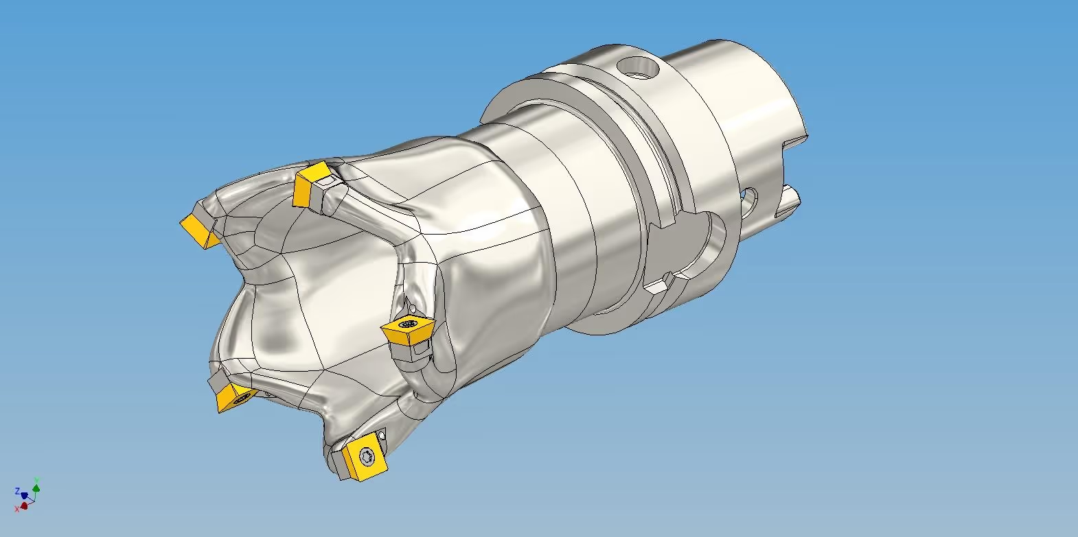
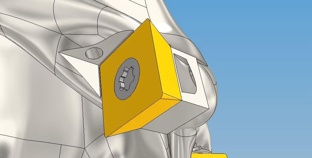
Additive manufacturing removes that constraint. Laser powder bed fusion (LPBF) builds the cutter body layer by layer, so internal channels can follow freeform paths from the HSK holder interface through the body and exit directly at each of the five insert seats. Every cutting edge gets targeted coolant flow instead of an external splash, with no compromise to the structural core of the tool.
What I did
- Shaped the cutter body, insert seats, and freeform internal channel routing using CAD and generative design.
- Verified the coolant flow through the internal channels with CFD.
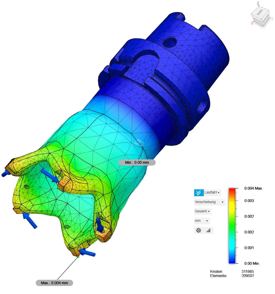
- Confirmed the structural stiffness of the cutter body under cutting loads with FEM.
- Designed the part for the LPBF process (DfAM) and prepared the geometry for manufacturing.
Results
The cutter was successfully manufactured via LPBF. The freeform internal channels came out of the machine as designed, something conventional manufacturing could not produce at all.
Figures